This tutorial is for those with some DIY hardware experience, though advanced beginners may find it a fun challenge. Also, experienced users might find it fun to set this up for beginners to learn from. To make this board without the SparkFun IoT Starter Kit with Blynk Board, you'll need sensors and other components to complete the built-in projects. For instance, the SparkFun Blynk Board comes with onboard WS2812 RGB LED, so you'll need a similar module to make projects using the device. You can purchase the components individually from Sparkfun.
I organize workshops in my local community to introduce people to open source hardware platforms such as Arduino and Raspberry Pi. With all the buzz around the Internet of Things these days, everyone wants to start tinkering and prototyping. The enthusiasts are usually designers, web developers, or students, and most want to get going with little coding.
ESP8266-based Blynk Boards come with preloaded projects and are ideal for introducing Internet of Things and basic electronics concepts.
About the hardware
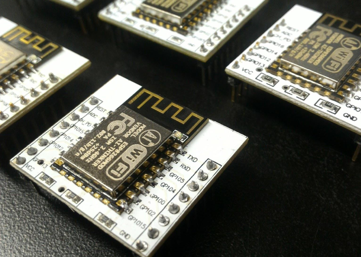
The ESP8266 is a great chip with built-in WiFi. It was originally used with Arduino boards to WiFi-enable hardware projects but soon became a cheap standalone Arduino-compatible development board. It comes in many shapes and forms and is most famous in development boards such as NodeMcu, Adafruit HUZZAH, or the SparkFun ESP8266 Thing.
David Egts wrote this terrific article about the ESP8266.
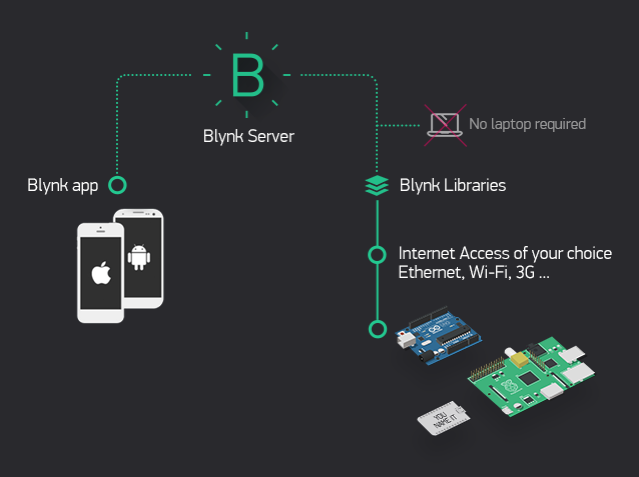
While the ESP8266 is great open source hardware for getting started with the Internet of Things, Blynk is an ideal platform to control Arduino, Raspberry Pi, and the like over the Internet. Essentially, Blynk includes three components: a Blynk app for the smartphone, the Blynk server, and Blynk library (firmware), which is compatible with a variety of makers’ hardware.
Both the Blynk server and Blynk library are open source, while the Blynk app is available free for iOS and Android. The Blynk app allows you to build a graphic interface for your IoT project by simply dragging and dropping widgets. Blynk includes widgets such as LCD display, Joystick, and Buttons so you can start hacking away with just an IoT development board.
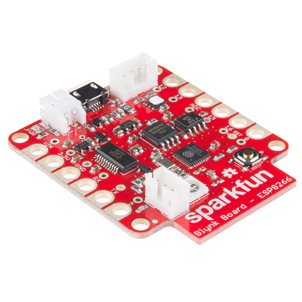
Blynk partnered with SparkFun to create the SparkFun Blynk Board based on the ESP8266. It comes fully programmed and includes more than ten pre-loaded Blynk projects. The SparkFun IoT Starter Kit with Blynk Board is a solid introduction to the world of Internet of Things (IoT) technology with no difficult programming.
If you're like me and have several ESP8266-based development boards lying around, you can use the firmware and turn them into DIY Blynk Boards. This would be ideal for running boot camps or workshops using existing boards. You'll still need sensors and other components to be able to complete the built-in projects. For instance, the SparkFun Blynk Board comes with onboard WS2812 RGB LED, so you'll need a similar module to make projects using the device.
Making a DIY Blynk Board
Gather the gear
- An ESP8266-based development board such as NodeMCU, Wemos D1, Sparkfun ESP8266 Thing, etc.
- Computer with Arduino IDE and proper drivers for development board
You should already be able to flash an Arduino sketch onto the development board. - USB cable to connect board to a computer
- WiFi network
- Smartphone
- An LED for testing
- Blynk app: iOS and Android
Before going any further, download the app to your smart device.
Install the required libraries
- Open the Arduino IDE
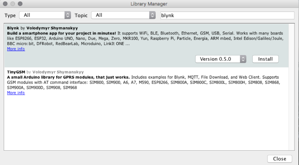
- Go to Sketch --> Include Library --> Manage Libraries

- Search for “blynk”, then install:
- Install the following additional libraries, using the latest version available:
SparkFun HTU21D:

Adafruit NeoPixel:

SparkFun TSL2561:

Flashing the ESP8266 board with Blynk Board firmware
- Download the Blynk Board firmware.
Extract the content of the zip file:
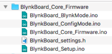
- Open any of the .ino files, which will open the Arduino IDE with several tabs:
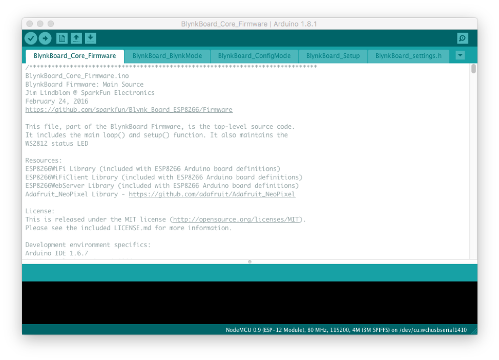
- Scroll down on the BlynkBoard_Core_Firmware tab and uncomment the line:
//#define DEBUG_ENABLEDComment the line:
#define SELF_TEST_ENABLED

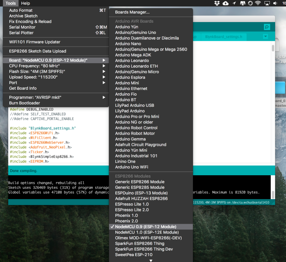
- Select the appropriate board (I’m using NodeMCU):
- Verify the sketch. The build should be successful.
- Connect your board to the computer via USB cable and upload the sketch.
The board is now flashed with BlynkBoard firmware.
Provisioning your DIY Blynk Board
In the provisioning process, we'll use a smartphone, laptop, or computer to connect directly (over WiFi) to the Blynk Board. Once connected, your smart device will send the necessary data and tell the Blynk Board to connect to your Internet-connected wireless network and Blynk.
The Blynk Board is initially configured to operate as a WiFi access point (abbreviated "AP," kind of like a router). A smartphone or WiFi-enabled computer can briefly connect to the Blynk Board, and using either the Blynk app or a browser, send all of the necessary information over to it. After the Blynk Board receives that info, it'll transition from AP to WiFi device and connect to your WiFi network. The AP has SSID in the format BlynkMe-XXXX:
Note: The SparkFun Blynk Board has a built-in RGB LED. When powered on, it blinks with a unique sequence (randomly allocated) of four colors, including either red, green, blue, purple, or yellow, with a long stop in between. If you have a WS2812 RGB LED, you can connect it to Pin 4. In my case, the LED would blink red, red, yellow, and then red.
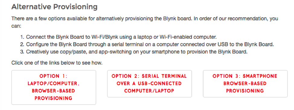
Follow one of the alternative provisioning methods in Sparkfun's Getting Started with the SparkFun Blynk Board tutorial.
Testing the board
(Source: SparkFun tutorials)
Blynk setup
1. Make sure your project is not running – the upper-right icon should be a triangular play button.
2. Touch anywhere in the blank gray project space. A toolbox should open up on the right side with all of your widgets to choose from.
3. Select the Button widget by tapping it. You'll find it at the top of the "Controllers" list.
4. Tap and hold the button widget to drag it anywhere within the project space. You've got a lot of room to work with right now.
5. Touch the Button Widget to bring up the settings page, and modify these values:
a. Name: "LED" – While the widget is a button, we'll be using it to control an LED.
b. Output: 5 – in the "Digital" list.
c. Color: Click the red circle to change the color of the button. Try blue, since we're toggling a blue LED.
d. Mode: Use “Switch” mode.
6. Confirm the settings:
If you're using an Android, hit the back arrow in the upper-left corner
If you're using an iOS device, hit the OK button.
Adding an offboard LED
Wire the LED as shown in the diagram below. The LED’s positive pin (the longer leg) should be connected to GPIO Pin number 5. Accordingly, on the NodeMCU GPIO 5 is Pin D1. Identify the correct pin for your board by referring to its pinout reference. The other LED pin should be connected to a ground pin (“GND”).
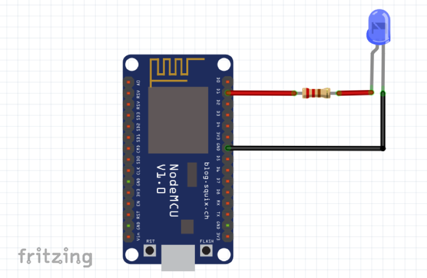
Blynk run
Now that the button is all configured in the Blynk app and the LED is properly wired to the board, run the project by tapping the Play button in the upper-right corner of the screen in Blynk app.
Once the project is running, tap the Button widget. When the widget is set to ON, the LED should also turn on.
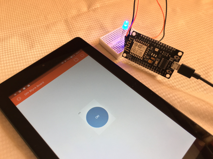
Congrats! You have successfully made a DIY Blynk Board. You can now follow the above steps for any other ESP8266-based boards you have, and gear up for introducing IoT to enthusiasts in your community.



8 Comments