A few weeks ago, my doctor told me to keep an eye on my heart with the help of DIY toolkit BITalino, and I wrote about it in Why my doctor prescribed me open hardware. Although I could keep slapping a bunch of cables and a PCB on me every day (Figure 1), miniaturized physiological computing devices are pretty fun to build and play with—at least for me—so I decided to make myself something more practical.
As this project may be of interest for others, I wrote this tutorial explaining the making of CubiKG, a Holter monitor-like device for heart and activity tracking. Also, to fit everyone's attention span, I provided the highlights, and a more detailed how-to that walks through each step to guide you through the building process.
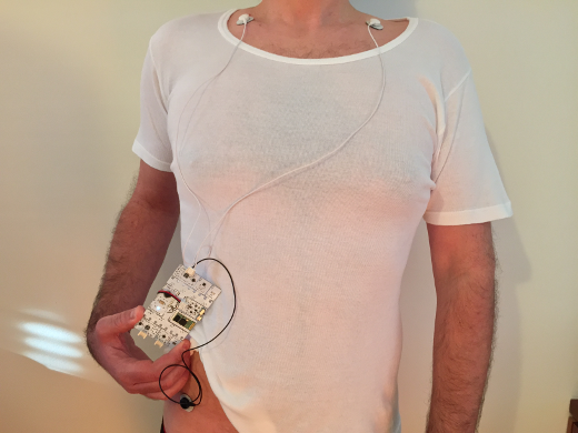
Figure 1: BITalino ECG placement in an equivalent to what is known as the Einthoven triangle.
Quick highlights
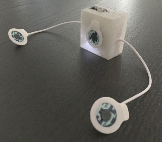
I've taken most of the parts seen in Figure 1, turned them into the CubiKG device shown in Figure 2, use OpenSignals for data recording or the BITadroid app by David Marquez (when on the go), and then look at the data using the Heart Rate Variability (HRV) add-on for OpenSignals.
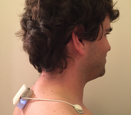
Figure 2: CubiKG device wearable that resulted from this build; it measures Electrocardiography (EKG) and motion data.
The data shows that before, the arrhythmias were clearly noticeable, as highlighted by the red point clusters (Figure 3, left). Now, considering what a typical IBI scatter looks like, all appears to be well, because the point cloud has a pretty normal spread (Figure 3, right).
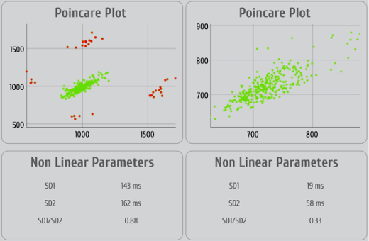
Figure 3: Pointcaré plot with the Inter-Beat Intervals (IBI) when I started to notice arrhythmias (left) and at the time of writing (right). Much better.
Along the way, I've managed to gather a basic set of tools that may help my doctor see how my heart is doing.
How to build the CubiKG hardware
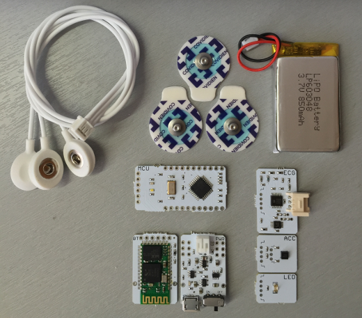
Materials: This build started off with a HeartBIT kit, namely an Electrocardiography (ECG) sensor, an accelerometer (optional), an LED (optional), an MCU, a power management module, a Bluetooth module, a 3-lead electrode cable, a few electrodes, and a battery.
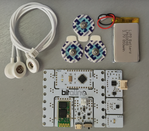
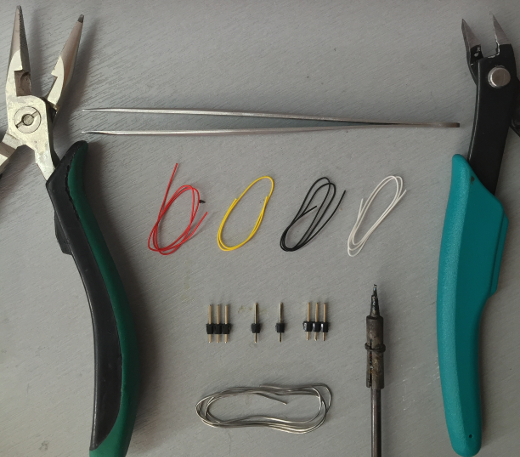
Tools: Most of these you either already have, or you can easily find in any general electronics shop (e.g., SparkFun), but you'll definitely need wires (the smaller, the better), tweezers, pliers (regular and wire cutters), header pins, and solder and a soldering iron. A glue gun and drill also will come in handy.
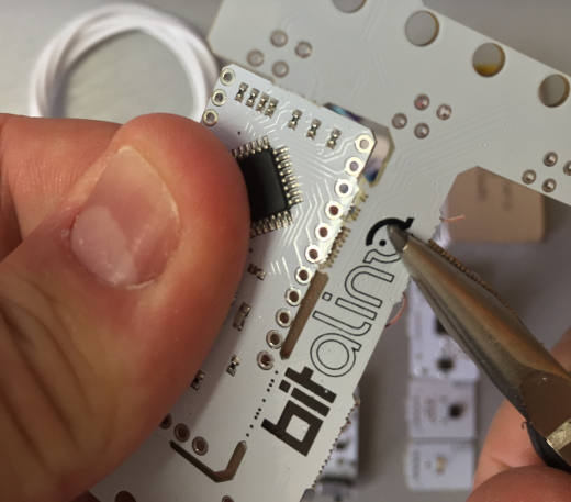
Step 1: Start by breaking off all the components. Most come out straight away if you jiggle them up and down a couple of times, but for the MCU, you'll want to be more careful and use pliers to help out along the way.
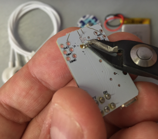
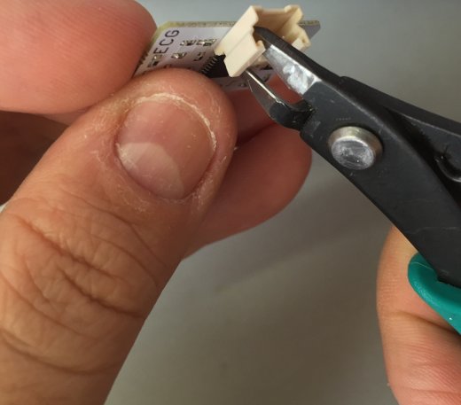
Step 2: Some of the parts (the ECG and the power module) have metal pins sticking out, which you'll want to clip off in order to achieve the smallest form factor.
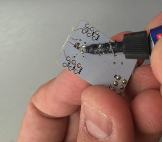
Tip: On the power block, applying glue or an adhesive that can isolate the battery pins to prevent short circuits is a good idea.
Result: From Steps 1 & 2 you should have ended up with this set of parts:
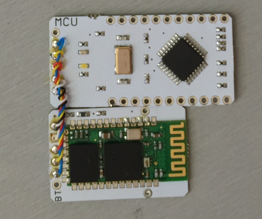
Step 3: Solder one wire up to each of the pins labeled TX (blue), RX (yellow), DVCC (red), STAT (white), and DGND (black) to the Bluetooth module.
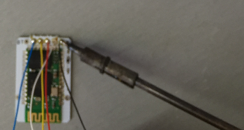
Tip: When using a small gage wire (as in this case), the heat of the soldering iron can be a great way to strip the wires.
Step 4: Trim the wires on the Bluetooth module to the length needed for each pin to reach its counterpart on the MCU and then solder each wire; a handy procedure may be to apply solder to each of the pins on the MCU.
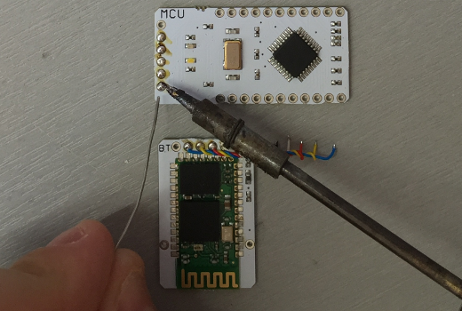
Then you'll just need to heat it and slide the wire into the molten solder.
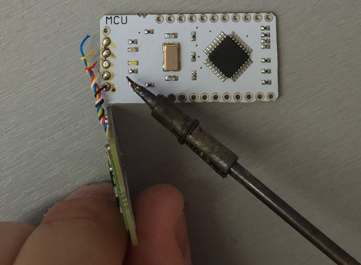
Result: After this step you should have the Bluetooth nicely matched to the MCU.
Step 5: Now its time to prepare things for the power block… solder header pins to DVCC, A6, DGND, AVCC, VSS, AGND, A5, and O1 on the MCU.
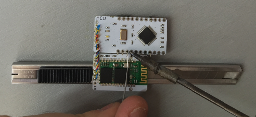
Tip: To get the thinnest form factor, generally I slide the pins from the bottom of the board up and trim the pins once soldered.
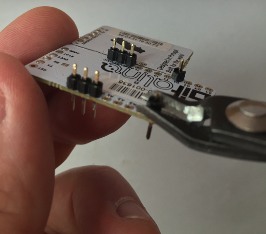
Result: After this step you should end up with a nice base for the power block to be slotted onto; note that I've also taken the chance to solder the holder pin on the Bluetooth module to I1 to strengthen the whole set.
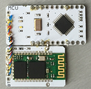
Step 6: Wire up at least pin A1 (to which the ECG sensor will be connected). For this build, I've chosen to make the device a little bit more complete, and added the optional accelerometer (for activity tracking) and an LED (for event signalling). If you'd like to do the same, in addition to A1, wire up A2, A3, A4, and also add two wires to O4, one of which you should solder to I1 (refer to the Final Result section for additional details).
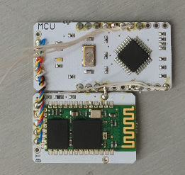
Tip: Also for event annotation, soldering O1 to I4 may also come in handy (refer to the Final Result section for additional details).
Step 7: Attach the power module to the header pins applied in Step 5 and solder them. To get a somewhat tidier device, I generally choose to run the channel wires (Step 6) through unused vias on the power module.
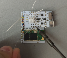
Tip: After this step you should already be able to run a few tests on your device, by connecting a battery, pairing it with the computer, and acquiring data using OpenSignals or the BITadroid app.
Step 8: If you're just using the ECG sensor, solder one wire to AVCC, another to VSS, and another to AGND. If you're also using the accelerometer and LED (as in my case), solder three wires to AVCC (red), one wire to VSS (yellow), and three wires to DGND (black).
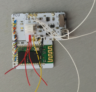
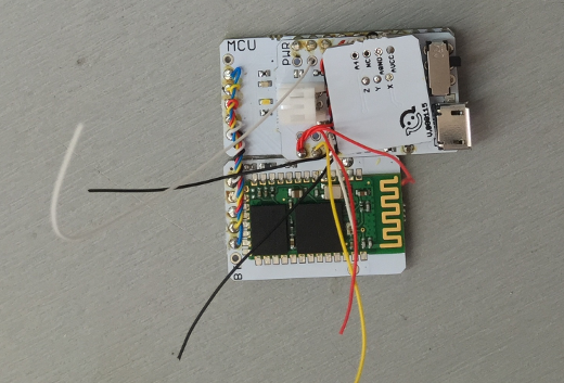
Step 9: Skip this step if you're just using the ECG sensor, otherwise take the accelerometer board and solder an AVCC wire (red) to the AVCC pin, an AGND wire (black) to the AGND pin, the A4 wire to the Z pin, the A3 wire to the Y pin, and the A2 wire to the X pin.
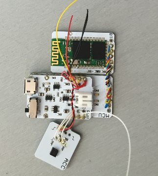
Then you can snug the sensor upside down onto the available space on the power module.
Tip: Next we're moving on to the ECG sensor, and a space-saving procedure is to use a wire cutter to remove the plastic housing on the plug.
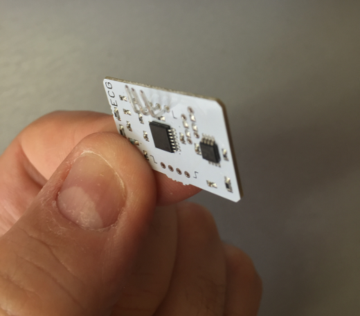
The result is much more compact assembly (see figure below).
Step 10: Take the ECG sensor board and solder an AVCC wire (red) to the AVCC pin, an AGND wire (black) to the AGND pin, the VSS wire (yellow) to the VSS pin, and the A1 wire from the MCU to the A3 pin on the ECG sensor board.
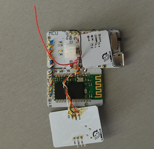
Tip: If you solder the wires with the sensor board upside down, they will be hidden on the final assembly as shown next.
Step 11: Flip the ECG sensor board to sit on top of the Bluetooth module. If you're using the LED also, solder an AGND wire (black) to the AGND pin and the O4 wire from the MCU to the O3 pin.
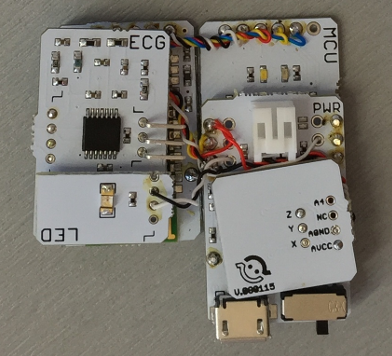
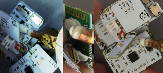
Step 12: Glue everything in place using, for example, a glue gun.
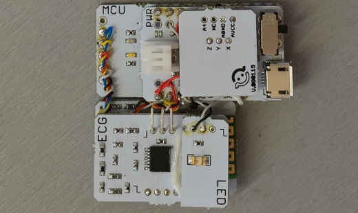
Result: The result of the previous steps should be a nice and compact hardware piece similar to this one.
Finishing touches
Step 1: Connect the electrode cables.
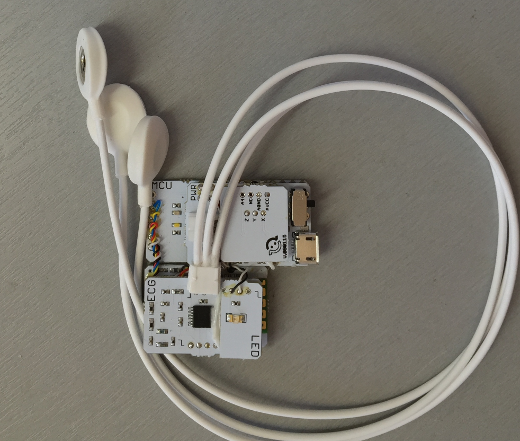
Tip: Clip off the locking mechanism on the plug to save additional space.
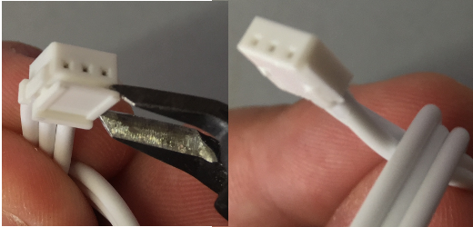
Step 2: Connect the battery. For me these things are all about achieving the smallest possible device, so I've actually used a 500mAh battery instead of the 850mAh battery shown in the materials, as it is a better fit to the footprint of this particular hardware arrangement.
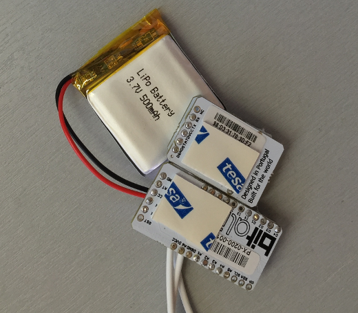
Tip: Add double-sided tape to the back of the MCU and Bluetooth modules in order to secure the battery in place.
Step 3: Arrange the electrode cables to your preference; in my case, I chose to make them the smallest length possible to make a more practical device, so the IN- and IN+ wires were wrapped around taking into account the distance between my neck (where the reference electrode will sit) and my collar bones (where the measurement electrodes will be attached).
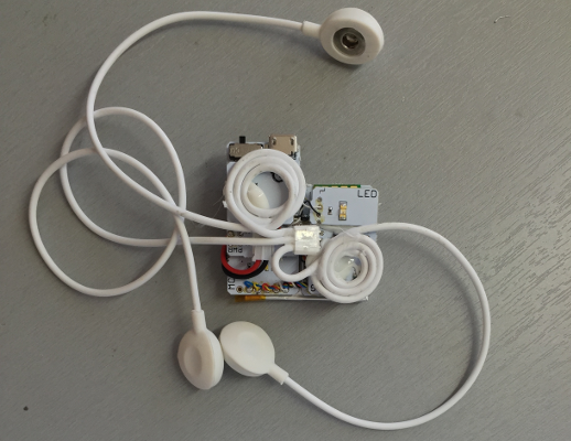
Tip: Glue the cables in such way that the IN+ and IN- come out of the device on an angle as straight as possible.
Step 4: I've wrapped around the reference electrode in such way that the snap connector sits on the center of the device (to have the unit nicely balanced around the approximate center of mass).
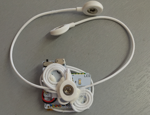
Tip: Steps 3 and 4 can be replaced by trimming the electrode cables to length and soldering them directly to the ECG sensor board; however, I find this particular setup to be better for future maintenance (e.g., the electrode leads can be more easily replaced if needed).
Step 5: Print out a casing suited to the overall size of your device (I've just scaled and printed out one of the 3D box models for the BITalino Freestyle)...
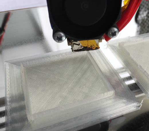
...and drill the holes for the reference electrode and for the IN+ and IN- electrode cables.
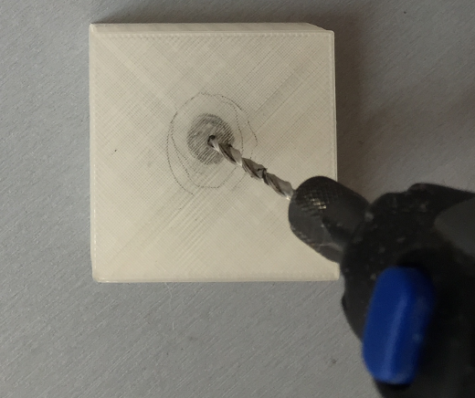
Tip: A clear material is advised for printing the model, so the LEDs can shine through.
Result
Using just the ECG shaves off a few steps from this build; however, this particular version of the device gives you a pretty cool set of measurements with ECG (A1), 3-axis motion data (A2-A4), and battery level (A6). Additionally, it also enables you to do event annotation, whenever you feel something different has happened (e.g., a stronger heartbeat).
If you followed the full tutorial, event annotation can be done in a "silent" way (by triggering O1) or with visual feedback (by triggering O4, which in turn activates the LED).
Connecting O4 to I1 (or another digital input) and O1 to I4 (or another digital input) is actually optional, as you can replicate the purpose via software; however these connections feed the triggering signal directly back to the device, giving you an easier way of storing the annotations together with the recorded data.
The CubiKG Device: This is it, a cube that can sense your heart, motion, and receive your events.
Software tools
Currently you can use OpenSignals (r)evolution for real-time visualization, recording, and replaying the data once stored. An add-on for Heart Rate Variability (HRV) analysis has recently become available, which greatly facilitates the process of extracting meaningful details from the data (e.g., Figure 3) that may be more easily reviewed by your doctor. Sometimes, it’s more convenient to go mobile (e.g., when roaming around the house or office), in which case, either the BITadroid app by David G. Marquez, or the BITalino DataLogger by Borja Gamecho are pretty handy.
Disclaimer
DIY hardware platforms, like the BITalino, are mostly educational tools, and they shouldn't be looked at as medical devices or used for medical diagnosis. If symptoms appear, always visit a licensed doctor.
All photos in this article are original images by Hugo Silva, CC BY-SA.
Hardware
A collection of articles on the current state and future of open hardware.


Comments are closed.